Using MATLAB and the 3D printer
Introduction
MATLAB is a program provided on all university computers (and can be accessed remotely through RAS) which serves a range of functions. For 3D printing, the main functions of MATLAB are to create surfaces or create data plots. Both of these results can be converted to .stl files, which can then be imported to software like Blender and edited to produce precise plots to be printed.
It is possible to take data from MATLAB and convert it into a 3D model. It can show 3 variables in the form of a heightmap, take 2 variables and extrude the data into a 3D object and .
Surface function
Below is a reminder of the Surface function (featured in the OpenSCAD manual) as it can be used with MATLAB to create a surface plot.
The surface(); function creates a surface by reading heightmap information from text or images. In text-based files, OpenSCAD requires an input of a matrix of coordinates, where the rows are mapped to the axis and the columns are mapped to the axis.
For example, if we type out:
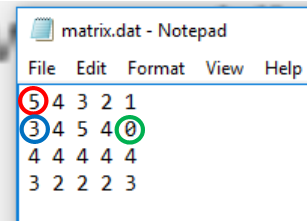
Then this would plot a surface which includes the coordinates at , , .
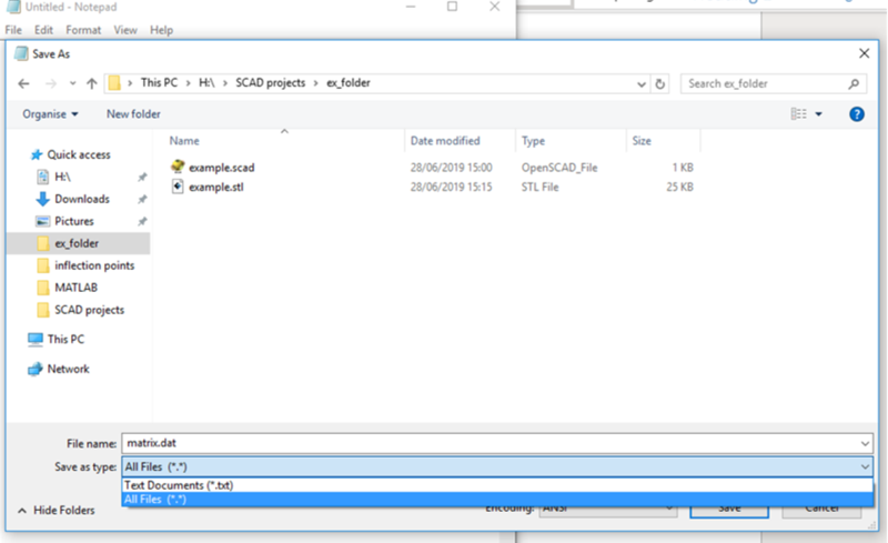
Then save this as a .dat file by clicking: File, Save As, then the drop down and selecting All Files (*.*). In the File name type out the name you wish to save it as then add .dat to the end.
To turn the .dat file into a surface, use the same method as importing an .stl file with two slight changes. First is to replace the word import with surface (to form the surface). The second is to replace the .stl with .dat after the file name (to read the file correctly).
surface("H:/SCAD projects/ex\_folder/matrix.dat");
As you can see, this function provides a base below the model to allow for solid printing. If you wish to reduce the size of this base, use the ’difference()’ function with this surface and a translated cube (larger side than the base) to remove the lower section.
MATLAB to OpenSCAD using Surface
An alternative to using the function grapher is to plot a surface using MATLAB then import it into OpenSCAD.
Say you wish to plot the surface given by the equation then you can use MATLAB to create a .dat file that outputs the coordinates in a matrix which OpenSCAD can read.
To do this use the following code:
% Creates a 2D grid coordinate grid from -1 to 2, in increments of 0.01
[X,Y] = meshgrid(-1:0.01:2);

% Equation of surface you wish to model
Z = 0.8*(cos(2*X)-0.5*Y.^2);

% Plots the surface for you to preview
surf(X, Y, Z);

% Adds a grid to the preview
grid on

% Sets any N/A values of Z to 0
Z(isnan(Z))=0;

% Exports the Z values into a .dat file and removes the default comma
% between values
dlmwrite('Data_points.dat',Z, ' ')
This .dat file will be saved in the same place as the default.
TIP: The smaller the increments of the meshgrid are (the value of 0.01 here), the more accurate a representation you’ll have. However, it is worth balancing out the accuracy of the model with the rendering time - as more complicated models (ones with more sides) take longer to render.
Increments of 0.01 will take a long time to render so it is worth changing this to 0.05.
Now we can open data in the surface function within OpenSCAD, however it will be incorrectly scaled. This is because OpenSCAD reads the .dat file with the difference between each coordinate as 1, rather than the value set in MATLAB (in this case 0.01). This is easily fixed by scaling in OpenSCAD after importing.
surface("H:/MATLAB/Data\_points.dat");
To correct with scaling, scale the and components by the value set in MATLAB (0.01 here) and the z component by 1 (not 0).
scale([0.01,0.01,1])
surface("H:/MATLAB/\\Data\_points.dat");
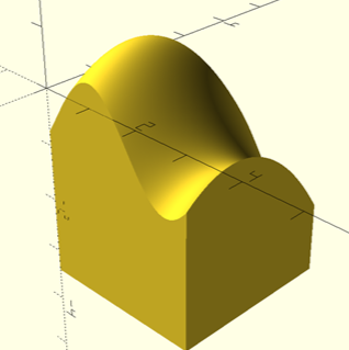
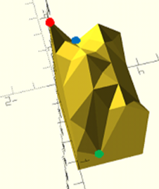
TIP: The surface is generated with one corner at the origin, however, in this case the coordinate system was between –1 and 2. This can be rectified using translate and makes modifying the model much easier if, say, we wish to cut along particular points (e.g. stationary points, points of inflection, etc.).
translate([-1,-1,0])
scale([0.01,0.01,1])
surface("H:/MATLAB/\\Data\_points.dat");
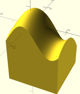
Notice how the translations for both x and y components are by their minimum values (in this case both –1), the code does NOT appear as ’translate([-1,2,0]);’.
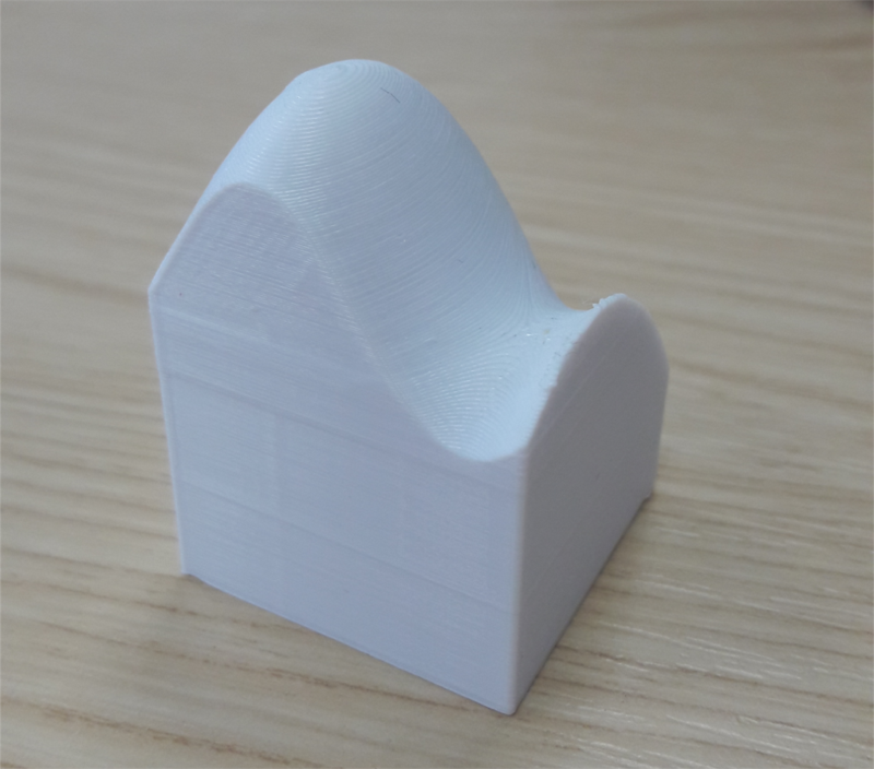
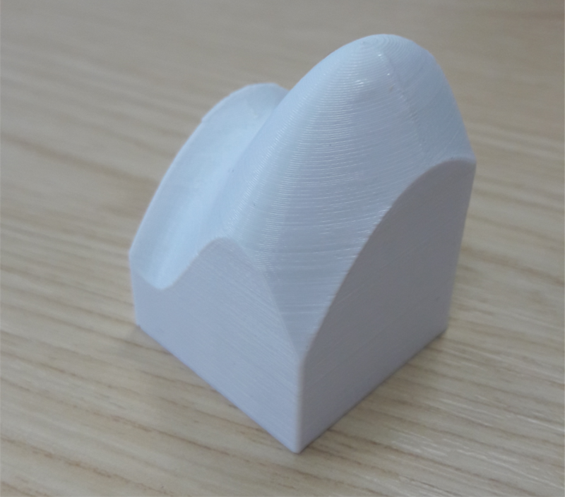
The model was then exported and scaled up to a printable size in FlashPrint ( as large, with a base 30mm 30mm).
MATLAB to .stl
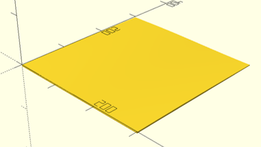
There are a few resources for transforming MATLAB code directly into an .stl file. One of which is surf2stl, in which you can either input faces and vertices or surface data in []. The method for using surface data results in the same as the method listed above, but cuts out the need to scale it in OpenSCAD. However, this method doesn’t provide the downwards extrusion into a rectangular flat base and will save the surface as a very thin .stl. Either of these may lead to poor quality prints if not edited in another software beforehand.
Links to manuals and tutorials
Things we’ve Made
Troubleshooting
Issue |
Cause of Issue |
Solution |
Models not importing |
Models may not be imported to OpenSCAD or other programs correctly |
Make sure the file path is correct with forward slashes used. Try to remove spaces and use - or _ between words as sometimes spaces between words can cause issues. |
MATLAB to .stl errors |
The model is assumed to be two dimensional as it appears on MATLAB which creates a very thin model |
Import the model to OpenSCAD as a surface or to Blender and extrude it, both of which gives the model thickness for better quality printing. |